Solar Absorber: Sizing and Z-Pattern Pipework
Solar absorbers heat the pool water free of charge using solar energy – provided the area, flow distribution and integration are right. By far the most common installation mistake is incorrect pipework, in which some of the absorber strips receive barely any flow and stay cold.
Sizing the absorber area correctly
The absorber area is the most important design parameter. As a rule of thumb, on a well south-facing, unshaded mounting surface you should plan for about 50 to 80 percent of the water surface as absorber area. If only an east- or west-facing surface is available, the tilt is unfavourable or you want to significantly extend the swimming season, you should increase the area to 90 to over 100 percent of the water surface.
More area means more heat input and at the same time allows a lower flow rate per square metre. Undersized absorbers, by contrast, heat the water only slowly and can barely counter the overnight cooling on cool days.
Include the local conditions in your sizing:
- Orientation and tilt of the mounting surface
- Shading from trees, roofs or neighbouring buildings
- Pool cover – a cover reduces heat losses considerably and noticeably increases the absorber’s effect
- Target season – early spring and late autumn require more area
Inlet at the bottom, outlet at the top – why direction matters
Solar absorbers are always filled from the bottom and drawn off at the top: the inlet is at the lowest point of the absorber field, the outlet at the highest. There are several reasons for this.
First, this fills the field completely and free of bubbles. Trapped air rises and escapes at the highest point via the outlet or an aerating valve fitted there. Air pockets reduce the flow, impair heat transfer and cause flow noise.
Second, the direction supports natural stratification: the warmed water rises to the outlet at the top. Third, the field can be completely drained in winter via the low-lying inlet. With the connections reversed – in at the top, out at the bottom – air collects in the upper region and parts of the absorber receive no flow.
Z-pattern pipework: the most common installation mistake
If there are several absorber strips or mats connected in parallel, they are joined via a distributor pipe (bottom) and a collector pipe (top). What matters is at which ends of these pipes you connect the inlet and outlet.
With correct Z-pattern pipework, the inlet and outlet are diagonally opposite: the inlet sits on the lower distributor at the left, the outlet on the upper collector at the right (or mirror-imaged). As a result, every parallel flow path through the field has almost the same total resistance – all strips receive an even flow. The routing forms a horizontal Z.
In the most common installation mistake, the U-configuration, the inlet and outlet sit on the same side. The water takes the shortest path through the front strips; the rear ones remain almost stagnant, cool and contribute little to heating. The efficiency of the entire field drops considerably.
| Feature | Wrong: U-configuration | Right: Z-configuration |
|---|---|---|
| Connection | Inlet and outlet on the same side | Inlet and outlet diagonally opposite |
| Flow | uneven, short-circuit through front strips | even across all strips |
| Rear strips | stay cool, water almost stagnant | fully flowed through and effective |
| Efficiency | considerably reduced | fully utilised |
Remember: Always connect inlet and outlet diagonally across – never on the same side.
Integrating the bypass and solar controller
The absorber is integrated as a bypass on the pressure side after the filter – this way only already filtered water reaches the mats. For the bypass, fit two tees into the pressure pipe (typically d50 (DN40) or d63 (DN50)). A ball valve acting as a throttle in the main line between the two tees forces part of the flow through the absorber; a further ball valve in the absorber branch allows it to be shut off completely.
Using the throttle, you set the balance between flow rate and temperature rise: a high flow brings a lot of heat at a small temperature difference, a low flow a warmer but smaller volume of water.
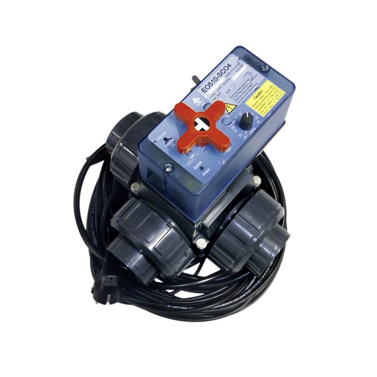
A solar controller (differential temperature control) is more convenient. Using two sensors, it compares the temperature at the absorber with the pool temperature and switches a motorised diverter valve: if the absorber is warmer than the water by a set amount, the water is routed through the absorber. At night or under a cloudy sky – when the absorber is colder – the absorber branch stays closed so the pool is not cooled down. An adjustable maximum temperature limits the heating.
If the absorber sits on the roof, a check valve prevents the line from draining or drawing in air when the pump is stopped.
For roof mounting, the structural loading must also be considered: a water-filled absorber field puts a considerable additional weight on the roof surface, and the flat-lying absorber must be secured reliably against wind loads – especially suction and lift-off. If in doubt, have the roof’s load-bearing capacity and the fixing checked by a structural engineer or specialist company, and follow the manufacturer’s installation instructions.
Draining before frost
Solar absorbers made of EPDM or polypropylene can burst if trapped water freezes. You must plan the frost draining as early as the pipework stage, not only in autumn.
Proceed as follows:
- Provide a drain point at the lowest point, the vent at the highest
- Lay the lines with a slight fall towards the drain point
- Shut off the absorber branch, undo the unions and let the field drain
- Carefully blow out residual water with compressed air at low pressure
Detachable unions at the absorber connections make seasonal removal easier. If in doubt, check the manufacturer’s specifications for the particular absorber and have the electrical and control integration carried out by a specialist company.
Integrating a solar absorber and piping it in a Z-configuration
- Determine the connection point Integrate the absorber as a bypass on the pressure side after the filter and fit two tees into the d50 (DN40) line.
- Size the absorber area Set the absorber area at around 50 to 100 percent of the water surface and divide it into parallel strips of equal length.
- Set the inlet at the bottom Mount the absorber field so that the inlet is at the lowest and the outlet at the highest point.
- Pipe in a Z-configuration Connect the inlet at the lower distributor and the outlet at the upper collector diagonally opposite, so that all strips receive an even flow.
- Fit the bypass with valves Fit a ball valve as a throttle in the main line between the tees and a shut-off valve in the absorber branch; use detachable unions at the connections.
- Add a check valve and controller For roof mounting, first check the load-bearing capacity and wind-safe fixing – if in doubt, by a structural engineer or specialist company – install a check valve, and fit sensors as well as a solar controller for the differential temperature control.
- Fill and vent Open the absorber branch, fill the field from the bottom and let the air escape completely at the top. Check all solvent-cemented and threaded joints for leaks.
- Ensure frost draining Lay the lines with a fall towards the low-lying drain point so that the absorber can be completely drained and blown out before winter.
Bill of materials
Example – please verify with a specialist. Parts and quantities depend on the installation; sizes shown are examples.
| Component | Size | Art. No. | KLN No. | Qty |
|---|---|---|---|---|
| 90° Tee, solvent socket, equal (PVC-U) | d50 | 70022 | 51512912 | 2 |
| 2-way ball valve M1, solvent socket (PVC-U) | d50 | 128814A | 51511559 | 2 |
| Cone check valve S4, solvent socket (PVC-U) | d50 | 121041 | 51510312 | 1 |
| Union Ocean, solvent socket / solvent socket | d50 | 170397 | 51512461 | 2 |
| PVC-U pressure pipe with socket | d50 | 76910 | 51515804 | 1 |
| 90° Bend, solvent socket (PVC-U) | d50 | 70979 | 51513442 | 2 |
| Griffon cleaner / degreaser | – | 1 | ||
| Griffon UNI-100 PVC-U adhesive | – | 20023 | 51512566 | 1 |
| Solar absorber (EPDM or PP mats or collectors) | – | – | – | Size the area to the water surface; inlet at the bottom, outlet at the top |
| Solar controller (differential temperature controller) | – | – | – | With absorber and water sensor; controls the diverter valve |
| Motorized 3-way diverter valve | – | – | – | Optional instead of a manual bypass, actuated by the solar controller |
FAQ
How large does the solar absorber area need to be?
With good south-facing orientation and no shading, about 50 to 80 percent of the water surface is sufficient. In an unfavourable location or for a longer season, plan for 90 to over 100 percent.
Why inlet at the bottom and outlet at the top?
This way the absorber fills completely, trapped air escapes upwards, and in winter the field can be drained completely via the low point.
What is the difference between Z- and U-pattern pipework?
With the Z-configuration, the inlet and outlet are diagonally opposite, so all strips receive an even flow. With the U-configuration on the same side, the rear strips stay cold.
Do I absolutely need a solar controller?
No, a manual bypass works too. However, a differential temperature control operates more efficiently and prevents the absorber from cooling the pool down again at night.
Does the absorber have to be drained in winter?
Yes. Freezing residual water can burst mats and collector pipes, so draining and blowing out before the first frost is mandatory.
This guide provides general technical orientation and does not replace professional planning. Safety-, electrical- and permit-relevant work must be carried out by qualified specialists.