Automating Valves: Electric and Pneumatic Actuators
Whether a valve actuator is electric or pneumatic has a decisive influence in process and plant engineering on response time, operational safety and running costs. Anyone looking to automate plastic valves such as ball valves, butterfly valves or diaphragm valves therefore faces the fundamental question of the right actuator type first of all. This guide explains how automated valves are constructed, how electric and pneumatic actuators differ, which selection and sizing criteria are decisive, and which typical mistakes should be avoided during automation.
Why automate valves?
A manually operated valve requires a person to be on site to set the desired switching state. In modern plants this is no longer practical for several reasons: processes run unattended, switching operations must be precisely reproducible, and for safety reasons aggressive or hot media should not be switched in the immediate vicinity of the operator. An automated valve actuator handles opening, closing or modulating in response to an electrical or pneumatic signal – reliably, reproducibly and remotely controllable.
Automation brings three key advantages: reproducibility (every switching operation runs identically), remote operability (integration into control and process control systems) and process safety (defined behaviour in the event of faults, for example through a safety position on loss of energy). The actuator is mounted onto the valve via a standardised flange – usually to DIN EN ISO 5211 – and transmits its torque to the valve stem.
Design of an automated valve
An automated valve always consists of three mutually matched components: the valve itself, the actuator and the control system together with accessories. These three levels must match one another mechanically, in terms of energy and in terms of signalling.
- Valve: the actual shut-off or control element – in plastic process valves typically a ball valve (90° rotary movement), a butterfly valve (90° rotary movement) or a diaphragm valve (linear stroke movement).
- Actuator: converts energy (electricity or compressed air) into a positioning movement and delivers the required torque. A distinction is made between rotary actuators for 90° valves and linear or stroke actuators for diaphragm valves.
- Control system and accessories: solenoid valve (in pneumatic systems), positioner, limit switches, position feedback and the higher-level controller that drives the actuator and processes the feedback.
A mounting bracket with a standardised connection pattern sits between the valve and the actuator. The ISO 5211 flange defines the bolt pattern and the square dimension of the drive shaft and ensures that actuators from different manufacturers fit the valve mechanically. Crucial to their interaction is that the actuator torque exceeds the break-away and operating torque of the valve with an adequate safety margin.
Electric or pneumatic valve actuator: the basic principles
The question of the right valve actuator – electric or pneumatic – can only be answered by looking at the available energy, the required switching speed and the desired safety behaviour. Both principles have clearly defined strengths.
Pneumatic actuators
Pneumatic rotary actuators convert compressed air (usually 4 to 8 bar) into a rotary movement via one or two pistons. Two basic types are distinguished:
- Double-acting: compressed air actively opens and closes. There is no defined rest position – without compressed air the actuator remains in its last position.
- Single-acting (spring-return): compressed air moves the actuator in one direction, and integrated springs automatically return it to a defined safety position on loss of compressed air (fail-safe, e.g. “de-energised/depressurised closed”).
Pneumatic actuators switch very quickly, are robust, compact and power-dense, and are outstandingly suited to high switching frequencies as well as to explosion-hazard areas, since no ignition spark is produced. The prerequisite is an existing, dry and filtered compressed-air network. For control tasks they are combined with a pneumatic positioner.
Electric actuators
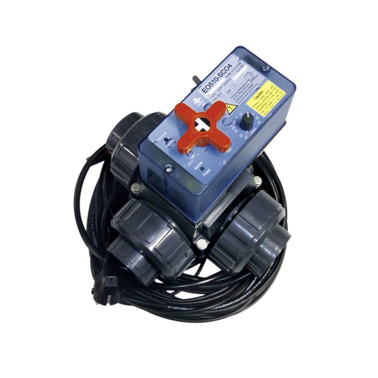
Electric actuators use a geared motor to rotate or lift the valve stem. They require only an electrical connection and manage without a compressed-air infrastructure. Their strength lies in precise positioning: intermediate positions can be approached exactly via an internal potentiometer or an absolute encoder, which predestines them for modulating control tasks. They operate more slowly than pneumatic actuators, but do so smoothly and with a defined torque curve.
Automatic fail-safe behaviour can only be achieved on an electric actuator with additional equipment – for example via a spring return or a capacitor- or battery-based emergency-movement module. Without this equipment the actuator remains in its last position in the event of a power failure. In explosion-hazard areas a correspondingly certified version is required.
Electric or pneumatic: the direct comparison
The following table contrasts the most important properties and serves as an initial orientation when selecting an actuator. It does not replace a plant-specific assessment, but it does help to establish the fundamental direction.
| Criterion | Pneumatic actuator | Electric actuator |
|---|---|---|
| Energy required | compressed air (approx. 4-8 bar) | electrical connection |
| Switching speed | very fast (seconds range) | slower, but precise |
| Safety position (fail-safe) | easy via spring return | only with an add-on module |
| Control / modulation | possible (with positioner) | very good, precise positioning |
| High switching frequencies | well suited | limited by motor loading |
| Explosion-hazard area | well suited (spark-free) | certified version required |
| Infrastructure | compressed-air network required | no additional infrastructure |
| Energy efficiency | compressed air is expensive energy | power drawn only during the positioning movement |
| Installation space / weight | compact, light | larger, heavier |
As a rule of thumb: if a reliable compressed-air network is available and fast open/close switching, high switching frequencies or a defined safety position are required, the pneumatic actuator is usually the more economical choice. If no compressed air is available, or the task involves precise, modulating control with rarely changing positions, the electric actuator plays to its strengths.
Sizing: torque and safety factor
The most common and most consequential sizing error is choosing an actuator that is too small. The decisive factor is torque: the actuator must reliably deliver the required operating and break-away torque of the valve under all operating conditions. This torque increases with nominal size, differential pressure, medium characteristics (solids, deposits) and the standstill time of the valve.
The following points must be observed when sizing:
- Safety factor: a safety margin is added to the nominal operating torque of the valve (in practice often in the region of 25 to 50 %) to cover break-away torque, wear and deposits. The specific values are specified by the valve manufacturer.
- Differential pressure: the operating torque depends heavily on the applied pressure. Sizing is carried out for the worst-case operating point, not for nominal operation.
- Type of actuation: rotary actuator (90°) for ball valve and butterfly valve, linear/stroke actuator for diaphragm valves – the movement type of the actuator must match the valve.
- Connection pattern: flange size and square dimension to ISO 5211 must match between valve and actuator; a mounting adapter may be required.
- Temperature: ambient and medium temperature affect both the permissible loading of the plastic valve and the limit values of the actuator.
It should be noted that the pressure rating (PN) of plastic valves decreases as temperature rises. An actuator correctly sized for cold operation may reach its limits at elevated medium temperature if the operating torque increases – which is why sizing must always be checked against the pressure-temperature behaviour of the specific valve.
Control, feedback and integration
An actuator alone does not yet make a functional automation. Only the control system and the feedback accessories integrate the valve meaningfully into the process. The peripherals typically include:
Actuation
In pneumatic actuators, a solenoid valve (pilot valve) directs the compressed air to the actuator. In electric actuators, the internal or external control electronics handle the approach to the end positions or intermediate positions. A digital signal is sufficient for open/close operation; for modulating operation an analogue signal (typically 4-20 mA or 0-10 V) or a fieldbus connection is used.
End-position feedback
Limit switches or a feedback module signal to the higher-level controller whether the valve has actually reached “open” or “closed”. This feedback is indispensable for process safety – without it the controller does not “know” whether the commanded switching state has really been assumed.
Positioner for control tasks
If the valve is to modulate to intermediate positions rather than merely open/close, a positioner is required. It compares the setpoint position (analogue signal) with the actual position and adjusts the actuator accordingly. On an electric actuator this function is often already integrated; on a pneumatic actuator a separate positioner is fitted.
For integration into a process control or automation system, the actuator, feedback and actuation are planned as a coordinated package. The appropriate actuators and the associated controllers and feedback components should be selected together early on, so that signal levels, protection class (IP rating) and explosion-protection requirements match one another.
Typical mistakes in automation
- Actuator undersized: the operating torque was chosen without an adequate safety margin or without accounting for the break-away torque – the valve no longer closes reliably. Always base the sizing on the worst-case operating point.
- Safety position not considered: in the event of loss of energy, a double-acting pneumatic actuator or a simple electric actuator remains in its position. Where a defined fail-safe position is required, spring-return pneumatics or an emergency-movement module must be planned in.
- Wrong actuator type for the task: an open/close actuator cannot modulate, and a pure control actuator is unsuitable for high switching frequencies. Clarify the actuation task (switching vs. modulating) before making a selection.
- Connection pattern not checked: flange size or square dimension to ISO 5211 do not match – the actuator cannot be mounted directly. Compare the connection patterns of valve and actuator in advance.
- End-position feedback forgotten: without feedback the controller cannot detect faults (e.g. a blocked valve). Plan in the feedback switches from the outset.
- Compressed-air quality underestimated: moist or contaminated compressed air leads to corrosion and failures in pneumatic actuators. Ensure conditioned, dry compressed air.
- Temperature influence ignored: a higher medium temperature lowers the permissible pressure rating of the plastic valve and can increase the operating torque. Check the sizing against the pressure-temperature behaviour.
Conclusion
Whether a valve actuator is electric or pneumatic is not a question of “better” or “worse”, but a trade-off along the lines of the plant requirements. Pneumatic actuators score with speed, high switching frequency, simple fail-safe behaviour and suitability for explosion-hazard areas – provided a compressed-air network is available. Electric actuators impress with precise positioning for control tasks and manage without a compressed-air infrastructure. In both cases, correct torque sizing with an adequate safety factor, the matching ISO 5211 connection pattern and well-thought-out integration of control and feedback determine operational safety. Anyone who plans actuator, valve and control system as a coordinated system obtains an automated valve that operates reliably, reproducibly and safely.
Frequently Asked Questions
Which is better: an electric or a pneumatic valve actuator?
That depends on the application. Pneumatic actuators are fast, robust, suited to high switching frequencies and explosion-hazard areas, and offer simple fail-safe behaviour via spring return – but they require a compressed-air network. Electric actuators need only a power connection, position very precisely and are therefore particularly suited to modulating control tasks. As a rule of thumb: compressed air available and fast switching needed → pneumatic; no compressed air or precise modulation required → electric.
How is the torque of a valve actuator sized correctly?
The actuator must reliably deliver the operating and break-away torque of the valve at the worst-case operating point. To do this, a safety margin is added to the nominal operating torque of the valve (in practice often around 25 to 50 %) to cover break-away torque, differential pressure, wear and deposits. The specific values are specified by the valve manufacturer; the sizing must additionally be checked against the pressure-temperature behaviour of the plastic valve.
What does fail-safe mean and how do I achieve a safe valve position on loss of energy?
Fail-safe denotes a defined safety position that the valve assumes automatically on loss of energy (e.g. de-energised/depressurised closed). On pneumatic actuators this is easily achieved via single-acting, spring-return versions. Electric actuators require an add-on module for this, such as a spring return or an emergency-movement unit with a capacitor or battery – without such equipment they remain in their last position in the event of a power failure.
Which standard governs mounting an actuator onto a valve?
DIN EN ISO 5211 is decisive for the connection pattern between actuator and valve. It defines the flange bolt pattern and the square dimension of the drive shaft on rotary valves and ensures that actuators from different manufacturers fit the valve mechanically. Before ordering, the flange size and square dimension of valve and actuator should be compared; in the event of discrepancies a mounting adapter is required.
Which components do I need in addition to the actuator for an automated valve?
In addition to the valve and actuator, automation involves the actuation (a solenoid/pilot valve for pneumatics, the control electronics for electrics), end-position feedback via limit switches or a feedback module and – for modulating operation – a positioner. For integration into a control system, matching signal levels (digital or analogue 4-20 mA/0-10 V or fieldbus), protection class and, where applicable, explosion-protection approval must also be coordinated.
Related guides
Similar Posts
Limescale and Water Hardness: Analyze Your Fill Water Before Filling the Pool
When you fill your pool for the first time, you inherit the water quality of your local supplier – with all its consequences for scale formation and material protection. A quick analysis of the fill water shows in advance whether and how you need to take countermeasures. Distinguishing Total Hardness, Calcium Hardness and Carbonate Hardness…
Disposing of Backwash Water Correctly: Sewer, Infiltration and Legal Requirements
Backwash water from the sand filter legally counts as wastewater and may not be disposed of the same way everywhere. This article explains the two disposal routes, how to deal with the chlorine content and how to reduce the volume produced. Backwash Water Is Wastewater, Not Just Pool Water During every backwash of a sand…
Plastic Ball Valves: 2-Way vs 3-Way in Process Engineering
A 2-way or 3-way plastic ball valve? This guide compares designs, bore variants and materials and shows what matters when selecting, sizing and automating them in process engineering.
SC04 Solar Controller: Automatic Control for Pool Solar Heating
Anyone heating their pool via a solar absorber faces a control task: the water should only run across the absorber field when there is actually heat to be gained there. That is exactly what the SC04 solar controller does – a complete set consisting of a control unit, temperature sensors and an electrically actuated Praher…
Sand or Glass Filter Media? A Comparison of Filter Systems
Sand or recycled glass as the filter medium? This practical comparison shows where glass filter media excels in filtration fineness, backwash water and service life, and when silica sand remains the right choice.
Permits and Building Law for Private Swimming Pools
Whether a private swimming pool needs a building permit depends on the federal state, the size of the pool and the location of the property. This overview shows what matters before you build and when you should involve the building authority. Building Permit or Exempt from Procedure? The Basic Distinction In Germany, building law has…